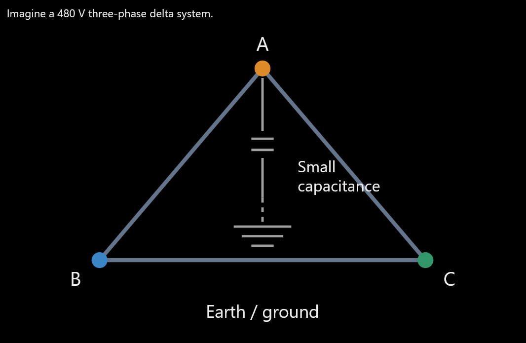
One thing we've been working on at the dam is getting reliable voltage readings when the turbine isn't running. Our electrical system is three-phase, and the generator appears to use a delta connection. Unlike a wye connection, a delta doesn't have a natural neutral point. This isn't normally a problem when measuring voltage between phases, but it can become a problem when measuring voltage between a phase and ground. The issue is that the voltage reference can float. Even though the phases still have the correct voltage between them, stray capacitance between the wiring and ground can cause our meters to show readings that don't really mean what we think they mean. When the generator is connected, its electrical configuration helps establish the reference that we're missing when it's disconnected. So we built a three-phase light-bulb array to help deal with this when the turbine is offline. It's a fairly simple solution to an interesting electrical problem. The important thing to understand is that having the correct voltage between three phases doesn't necessarily mean that their voltages relative to ground are well-defined. That's the part we're trying to account for with the bulb array.
Odds and Ends
Posted as if it was on: September-January, 2025
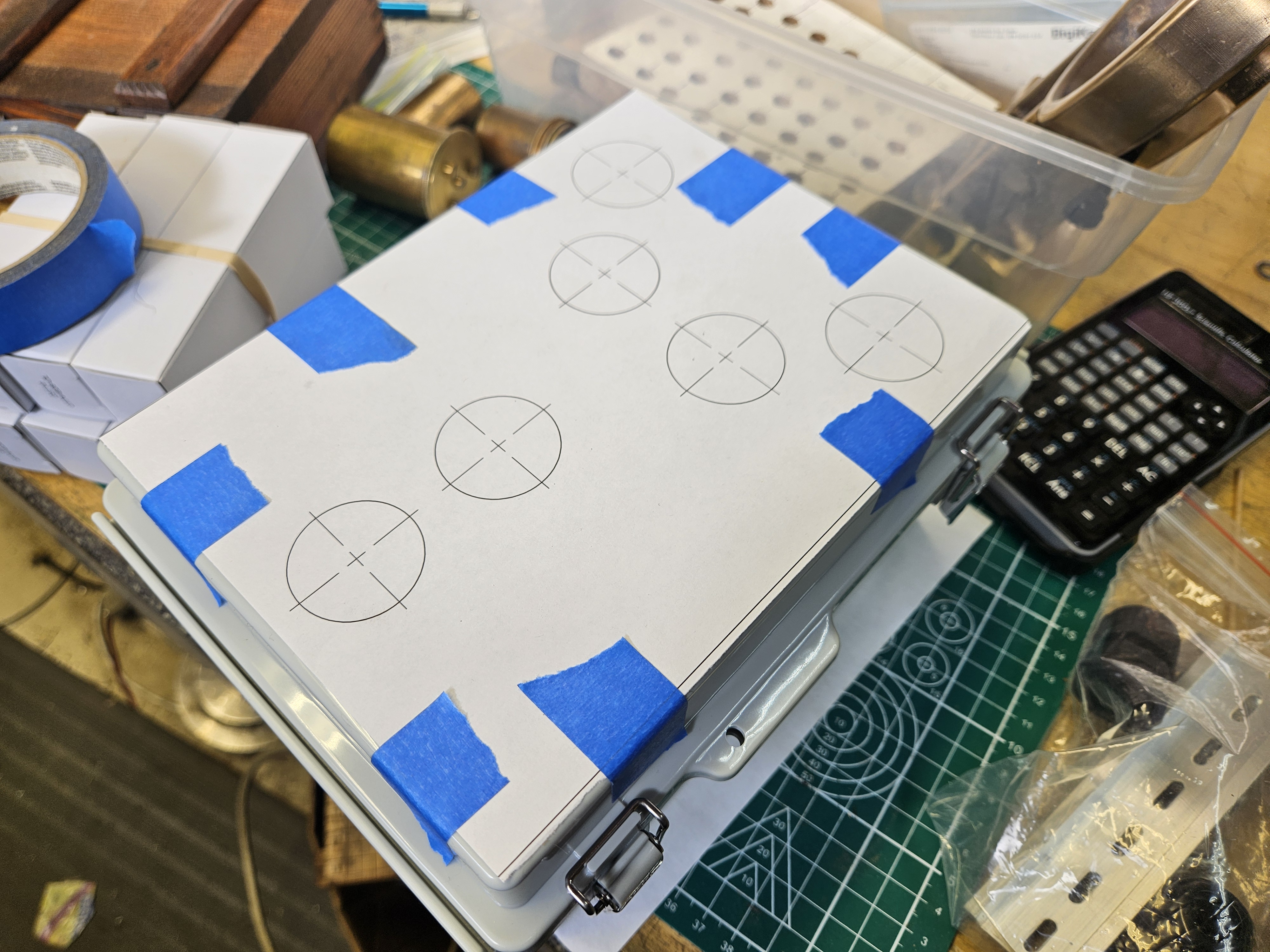
So Heres the layout for the 3 phase lightbulb box. It's amazing how many project boxes we use. Its very easy for us to take a problem and compartmentalize it make it into a box and then just install it. Rather than doing everything on site where we dont have all the tools in the world, everything can be done in the shop then basically plugged in.
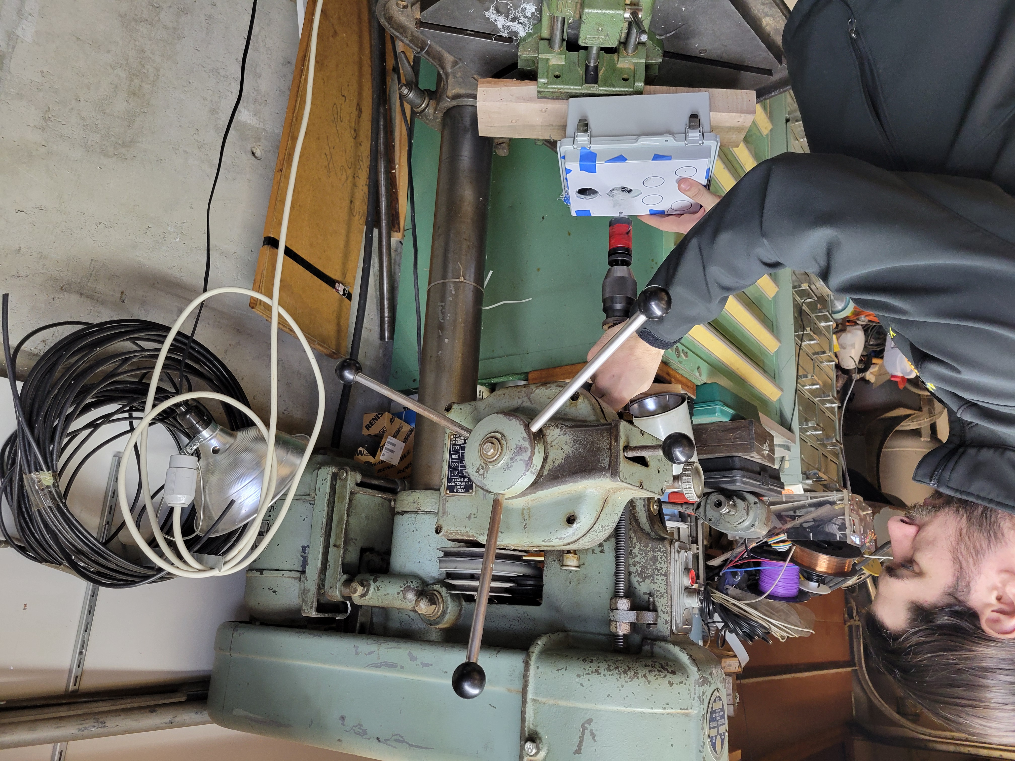
The box is made of resin and fiberglass usually, so pretty easy to work with, and when precision isnt needed, then you can print out the layout 1:1 and then tape it on and bob's your uncle just hole saw out the pattern.
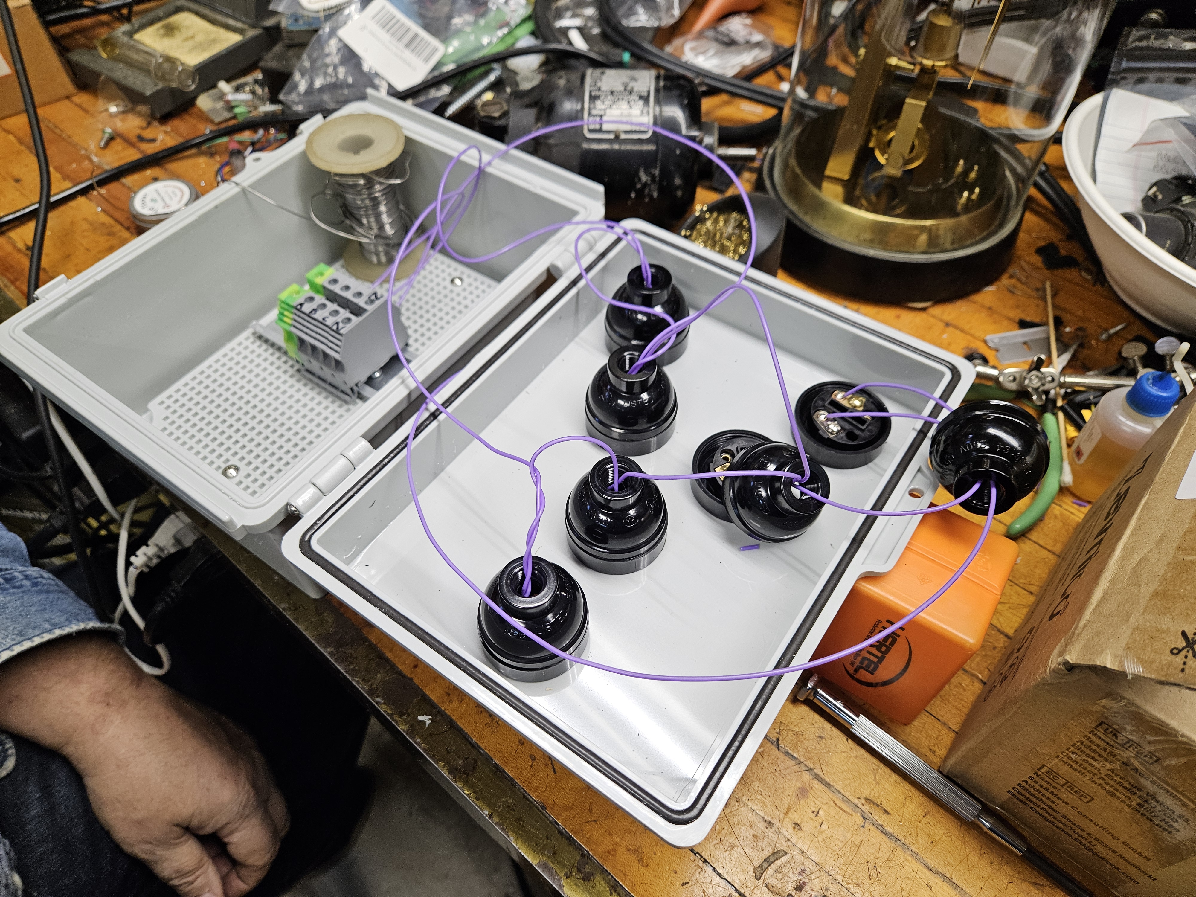
Here you can see all the lightbulbs hooked up. Also these are 277v lightbulbs but we are running each set in series, one beacuse we dont need that much power draw and second because they will last for forever. So rather than one bulb at 100w each, so 300w for this thing-a-mabob, its about 10-20w each bulb, and according to the ai gods the bulb shoud last 4,096 times longer, so from about 2000 hours to millions of hours.
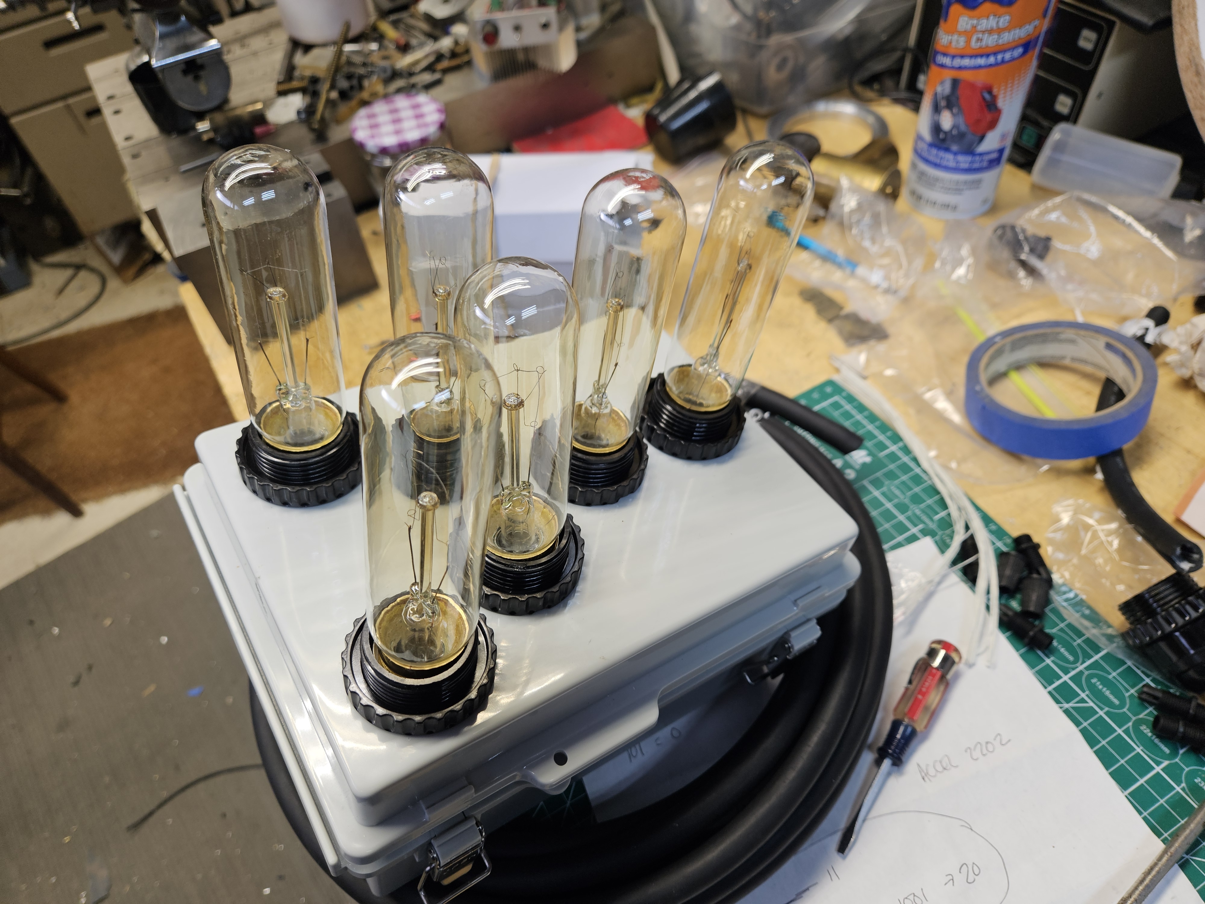
Here is the box all ready to go, it simply has a plug on it and we put a socket on our main panel. Plug and play, if one day things get reconfigured or what havbe you we can just move this thing and plug it in somewhere else. Hardwiring things can get annoying and is just less flexible in the future.
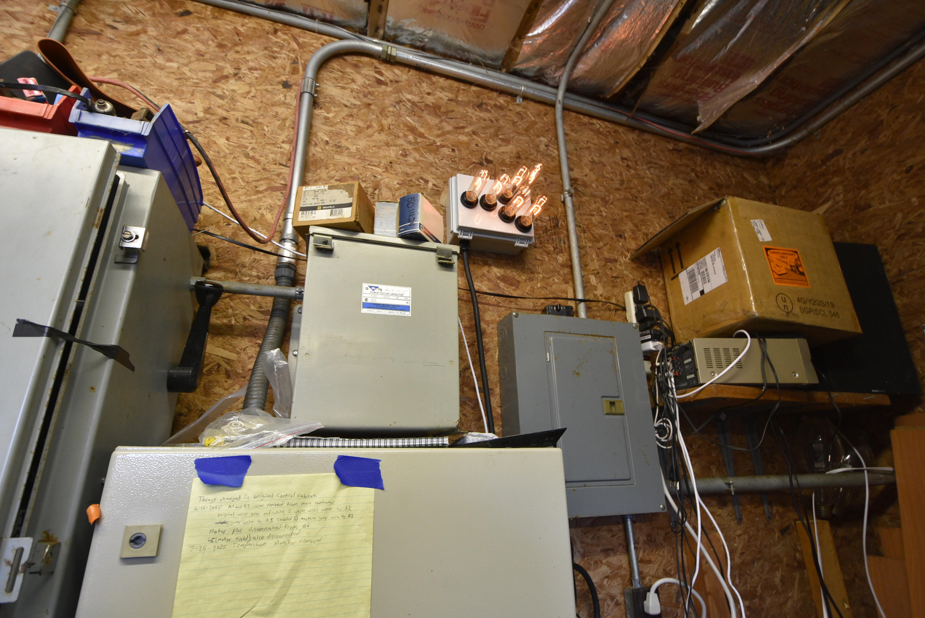
As you can see everything installed and it makes a great nightlight. Onto the next problem.
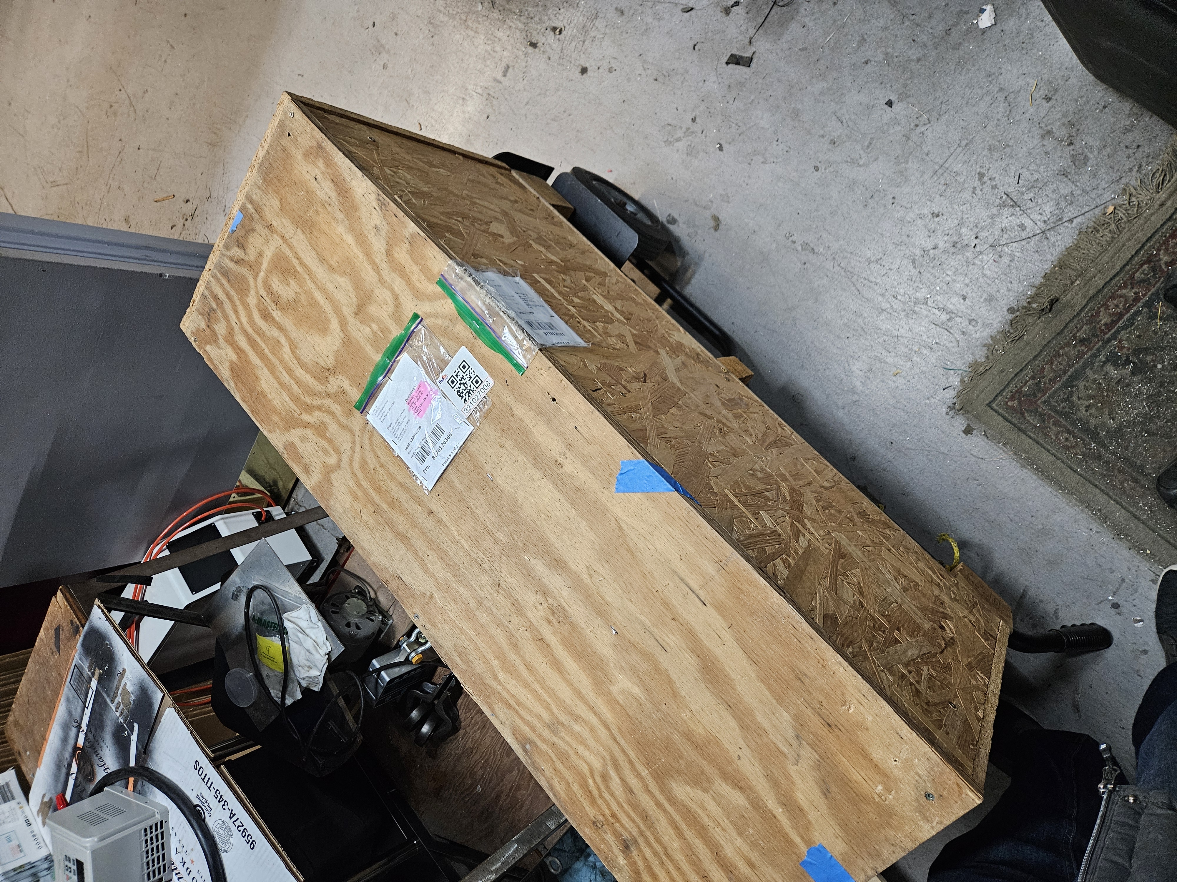
We got a special delivery from a friend who runs some small hydro down in North Carolina. He has a couple small sites, and runs his stuff on VFD's or Varable Freqeuncy Drives. These magic boxes allow you to change the speed of the turbine while still outputting the same voltage to the grid.
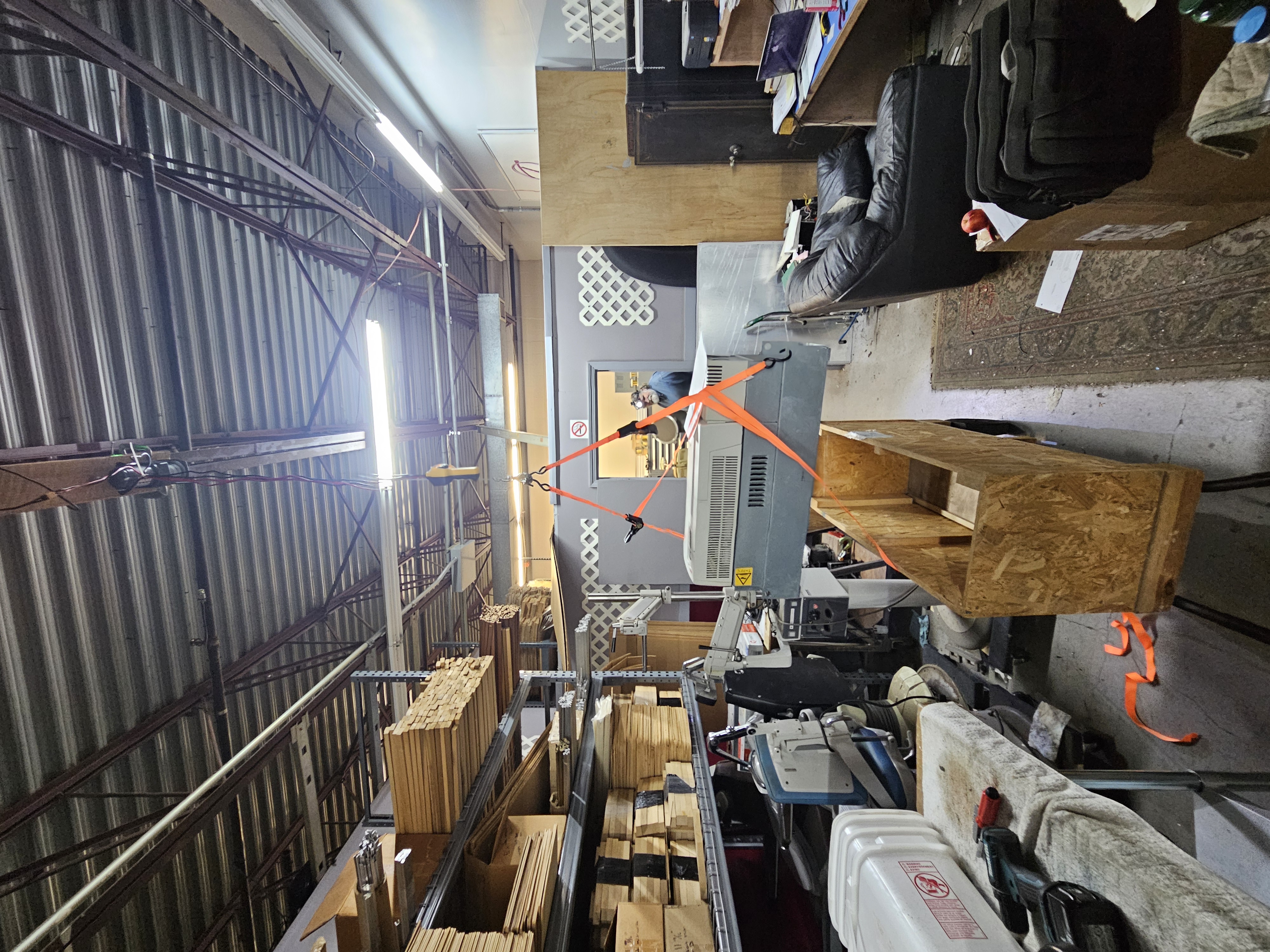
This particular VFD was extra stock he had laying around for a long while and it just so happens to fit out system perfectly. Its a 110kw unit, but whats special about this one is that it can export energy back to the grid. Most VFD's are made to run a compressor or a milling machine or machines with motors. And energy goes in and then you can change the speed of the motor. But if you wanted to say have a conveyorbelt full with rocks going downhill or a ski gondola, theres energy in the system and you would rather put it back into the grid than just into resistors. So theres a magic box in this magic box that allows for the variable speed, this one has a second magic box that then exports that energy to the grid at the proper phase and voltage. These are not as common in the real world.
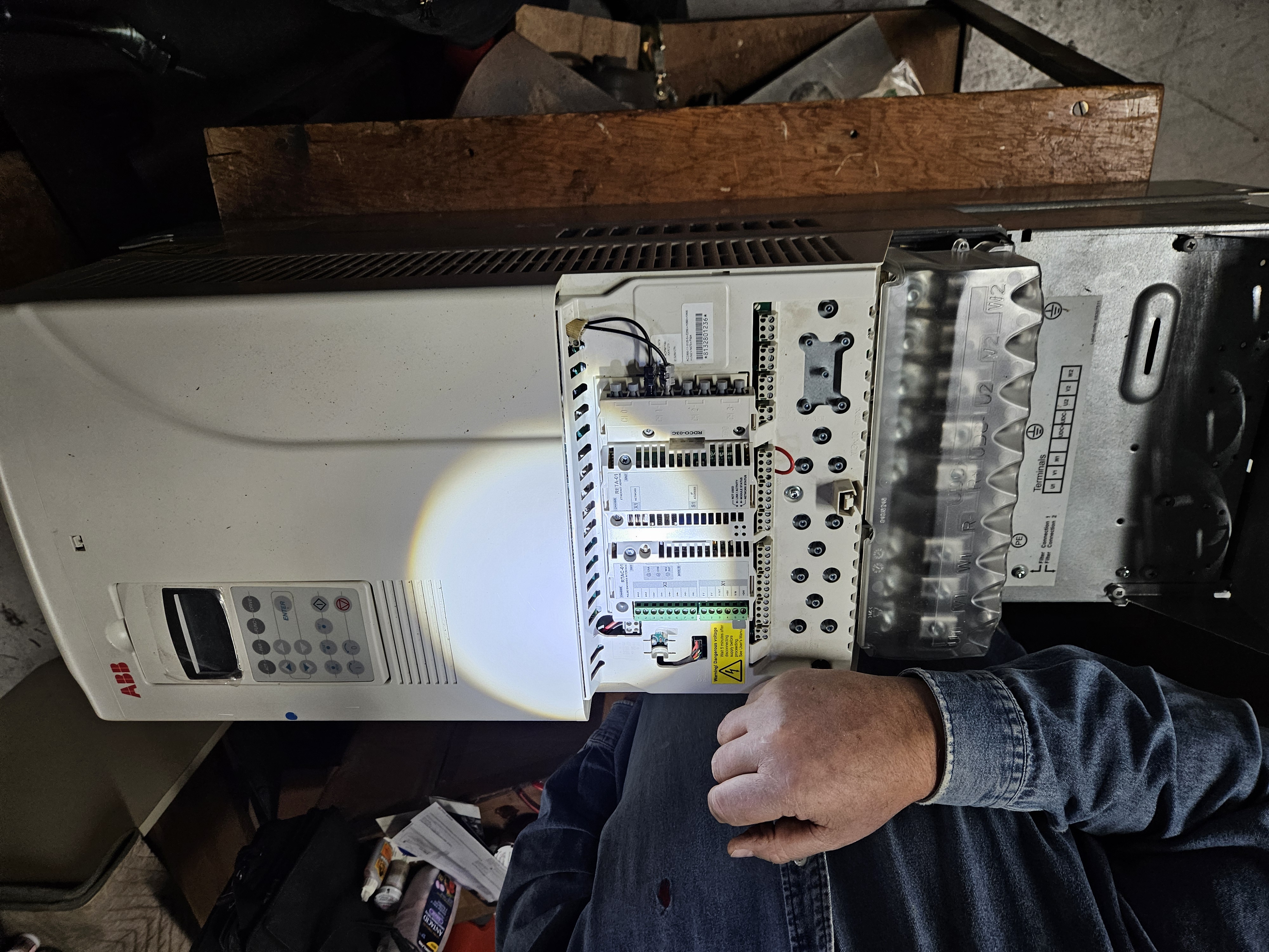
When we unboxed it we knew there was a problem with it. When the guy who sold it to us tried to power it up prior to shipping he couldnt get it to wake up. So we started to inspect whats going on.
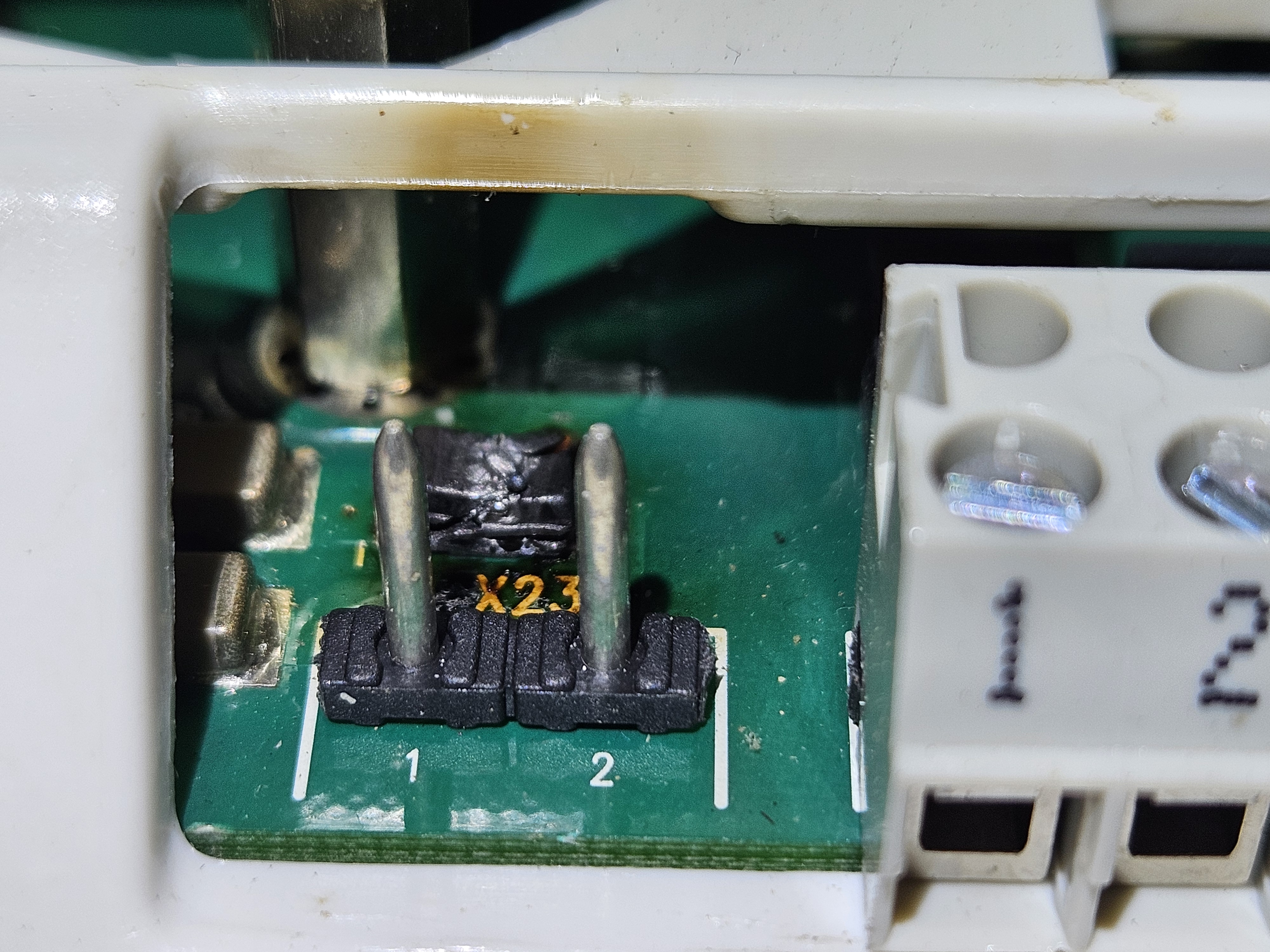
Ah ha! I found the reason why it was sad. These two pins are the external 24v power supply input. And right above the pins there should be a protection diode so that you cant plug it in backwards. Electronics dont like being plugged in backwards.
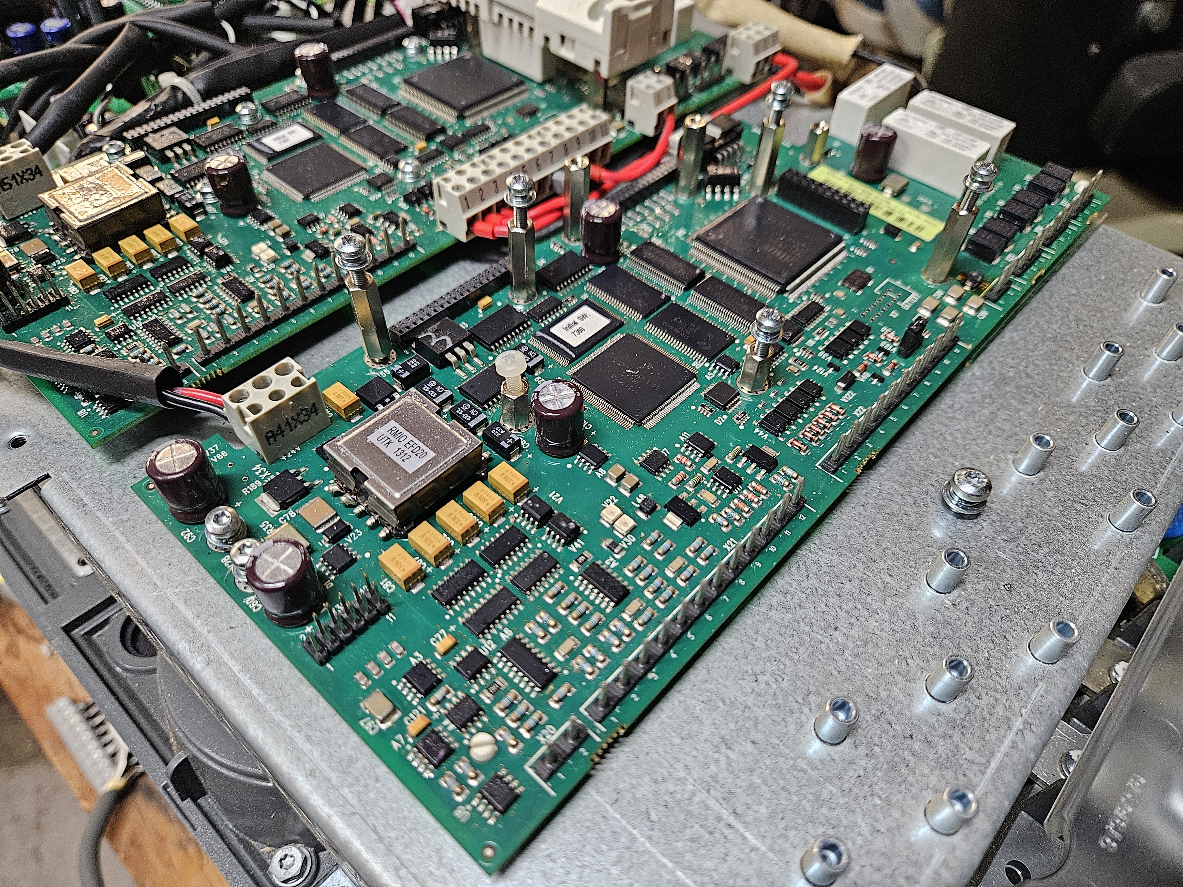
So we found the part number for the diode replaced it, no big deal.
After fixing the diode, we plugged in the external 24v logic supply and as you can see it comes to life. There was one problem however. If you have ever dealt with industrial sort of stuff where theres a company, a distributor, and sales departments based on your region, you will know my pain. So ABB is the maker of the drive, and when you buy a drive usually they set them up for a particular use case, air conditioning, cranes, milling machine. These things are called programs, where they have a bunch of preset parameters or programs. However when you want to reuse something that was setup for something else, oh billy. This particular drive was setup by a OEM in italy for hydro, but using a permanent magnet generator, not a induction motor. We were told we will need a new control board to change the program. I figure well its a program we could probably just flash the default program on and bingo. Well like 5 people 20 emails, phone calls across the world, I could not find a single person to help me. They all didnt have stock firmware for this drive. So ripperoni, after much much effort and ABB software and special Fiber communication magic boxes, we bought a new old board on ebay. Absolute failure but we learned a lot on the way.
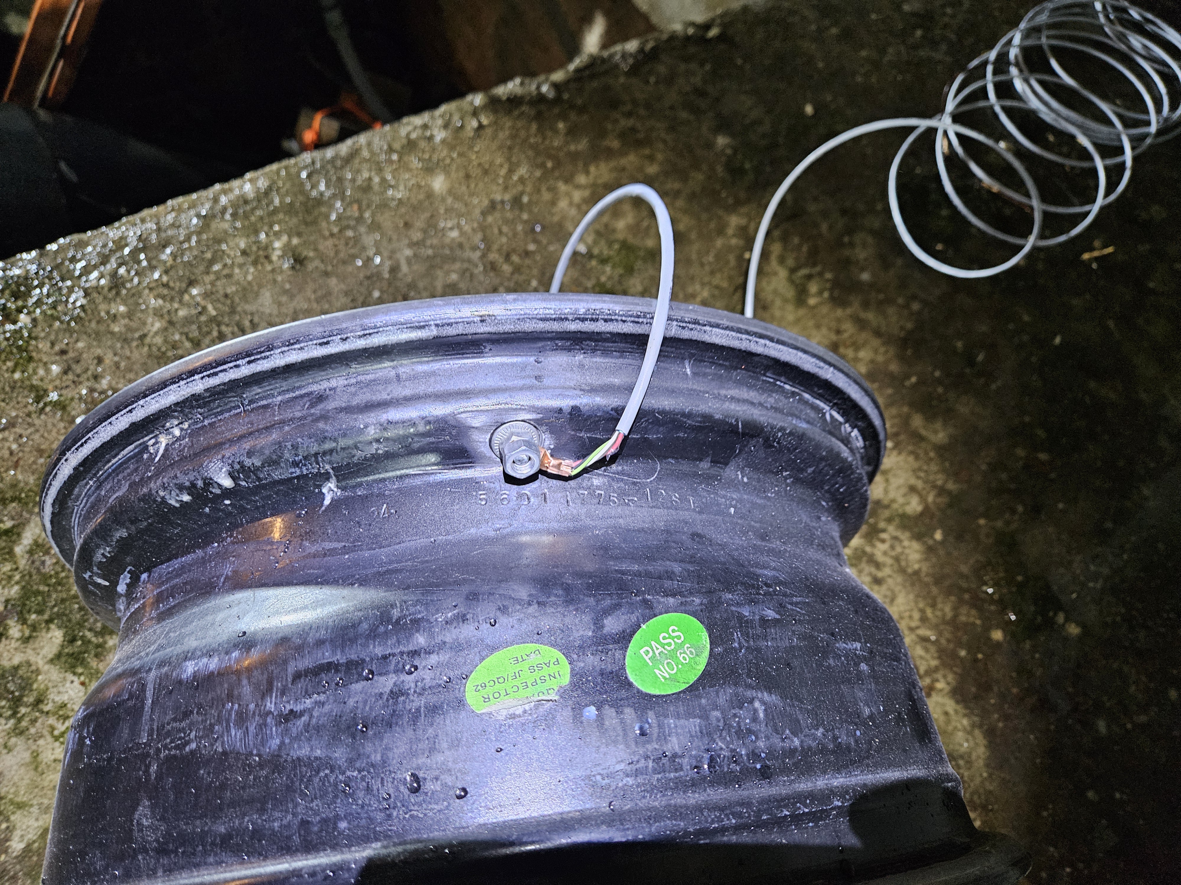
Another thing to check off the list, as you can probably see in the pictures, the steel skeleton that holds up the place is a tad rusty. So to slow down the rust we figured lets do a sacrificial anode. We recently got a new set of aluminum rims for my dad's car and one of the old ones was bent. So we made a bolt setup for the valve hole with a locking washer that digs in, and sanded the interface.
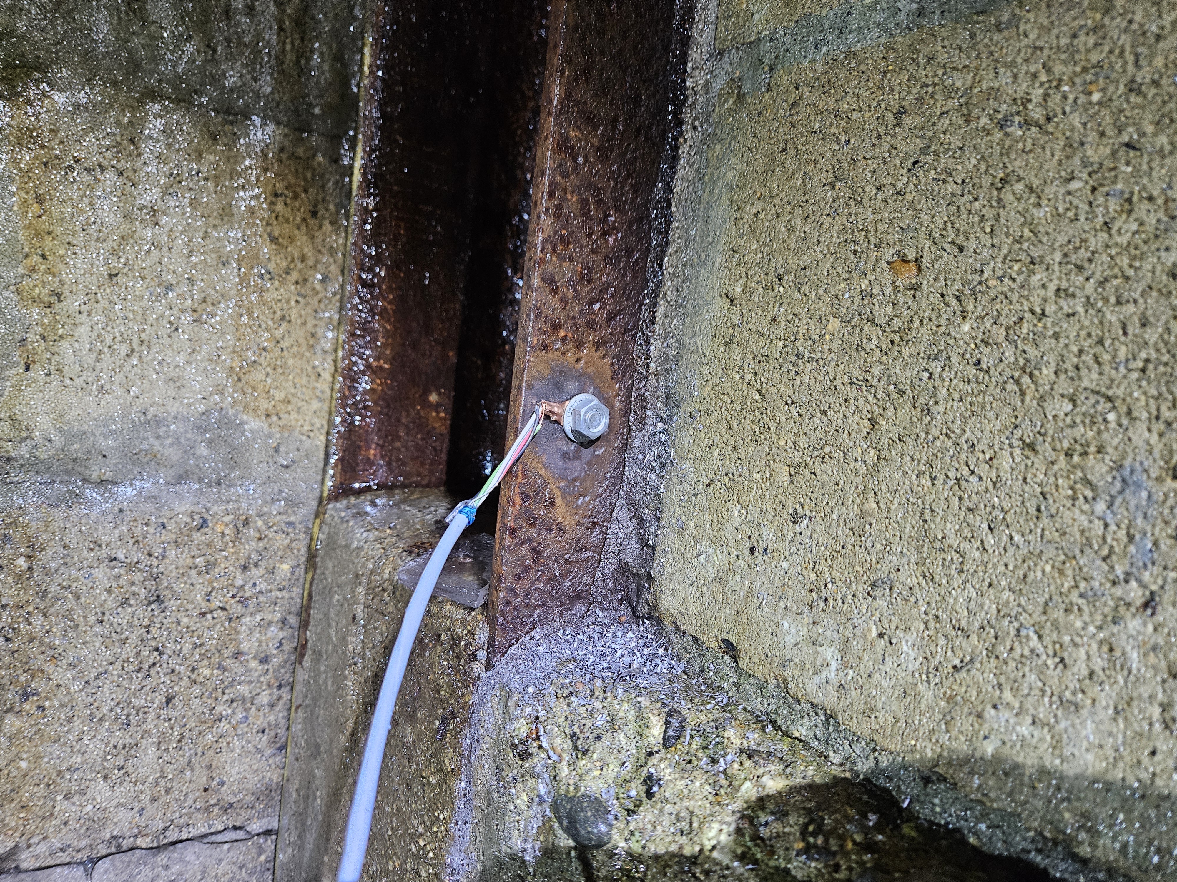
The other side of the wires goes to a cleaned patch on the beam on the wall, where i drilled a hole and attached said wire.
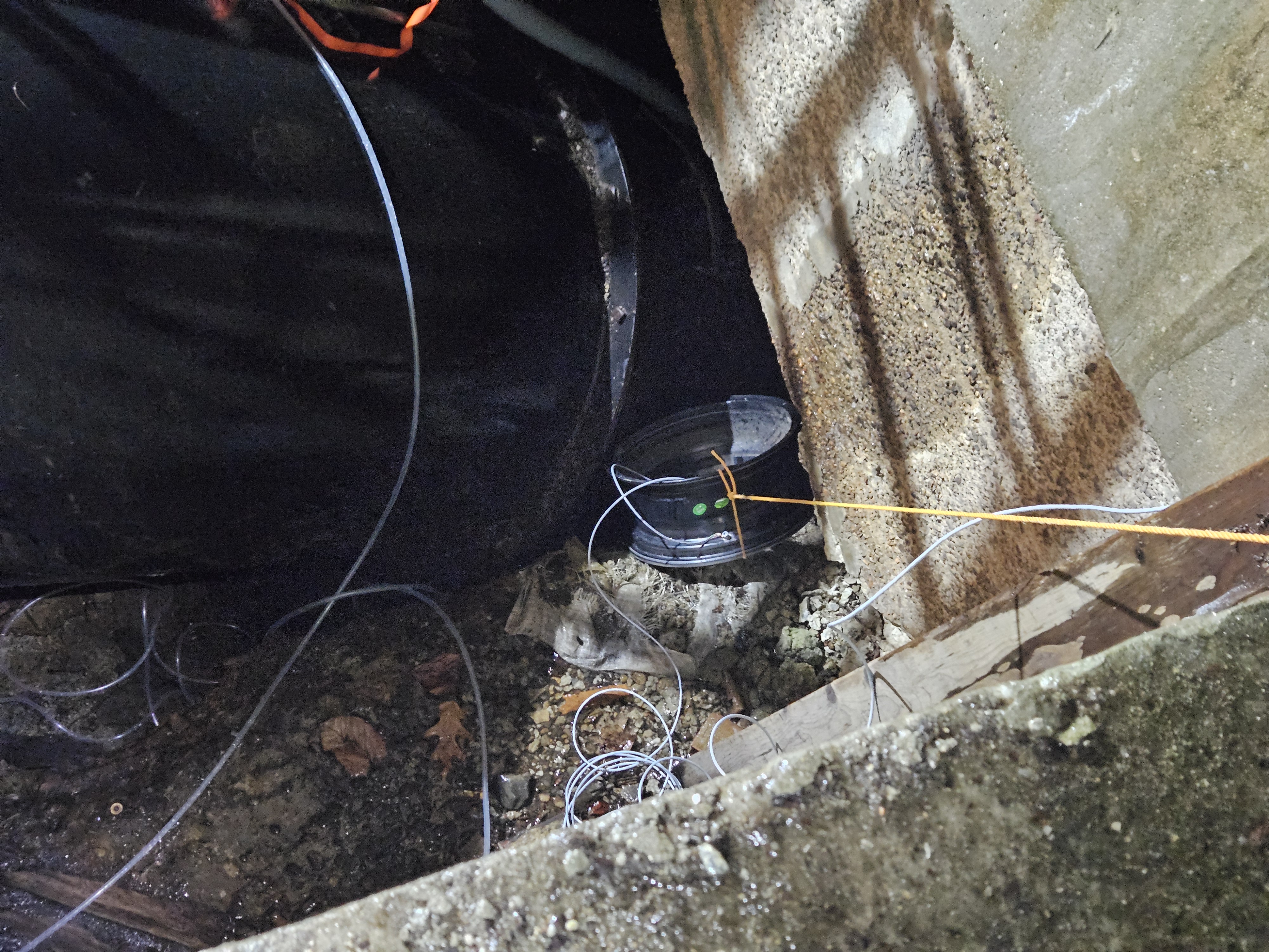
We tied a rope to the rim and lowered it down the side of the turbnine pit into the river. Also tied the rope up to the wall so we can lift it in and out if we needed to.
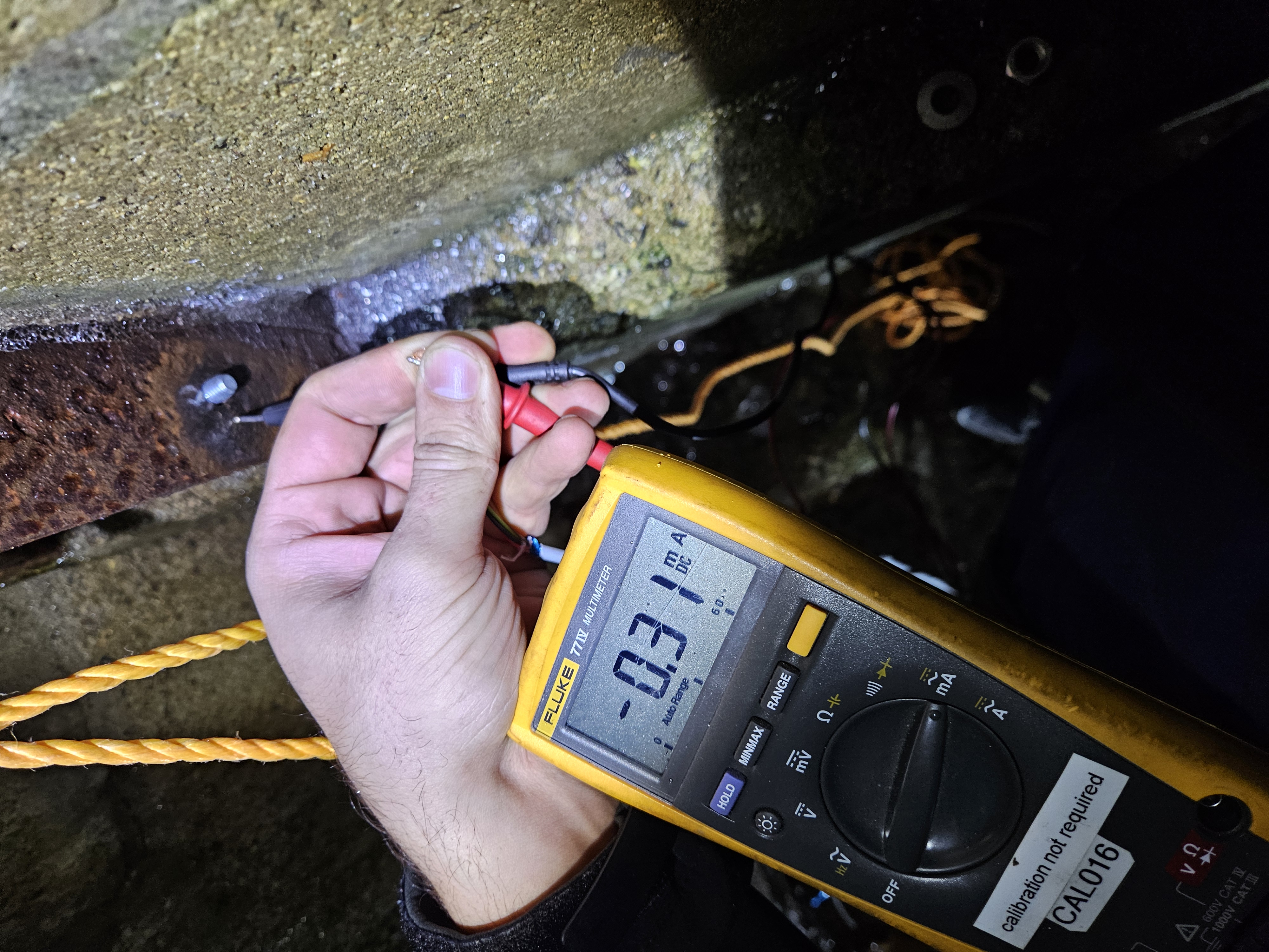
We wanted to see how it was working so we hooked it up to a meter. We are getting about 31mA, not too shabby.
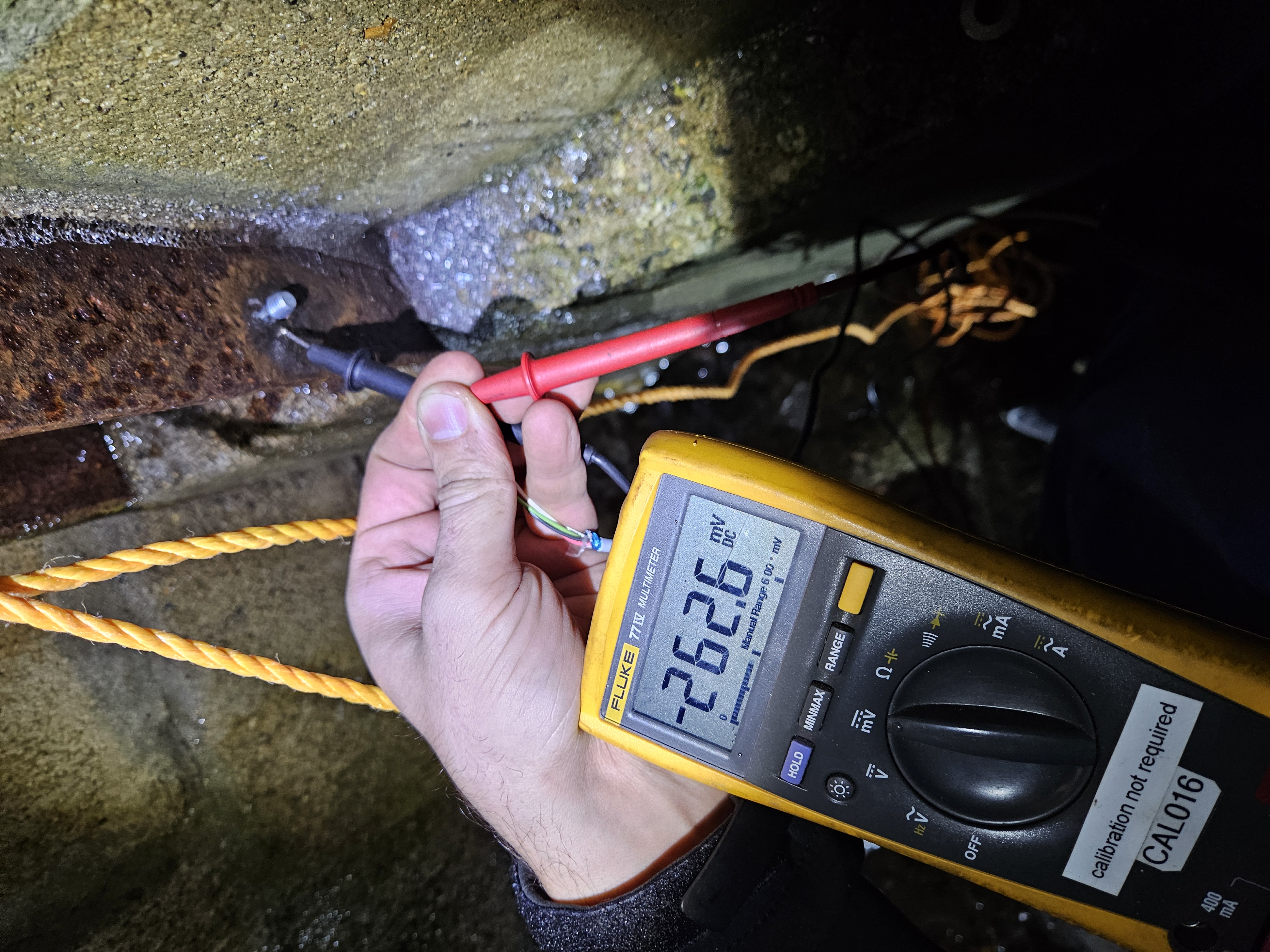
The idea is pretty simple. When two different metals are electrically connected and exposed to water, they can form a small electrochemical circuit. Aluminum is generally more chemically active than steel, so it can corrode preferentially, effectively sacrificing itself to help protect the steel. We connected a wire from an aluminum rim to the steel beams and submerged the rim in the river. So far, we're measuring about 262 mV between the two metals and 31 mA of current through the connection. That tells us the two metals are interacting electrically, although we'll need additional measurements to determine how effectively the steel is being protected. The goal is to have the aluminum slowly corrode instead of the steel. It's the same basic principle used to protect boat hulls, docks, and other metal structures exposed to water. Eventually, the sacrificial anode gets consumed and needs to be replaced, but that's a lot easier than replacing structural steel. It's a simple experiment, and we're interested to see how well it works in the conditions at the dam.
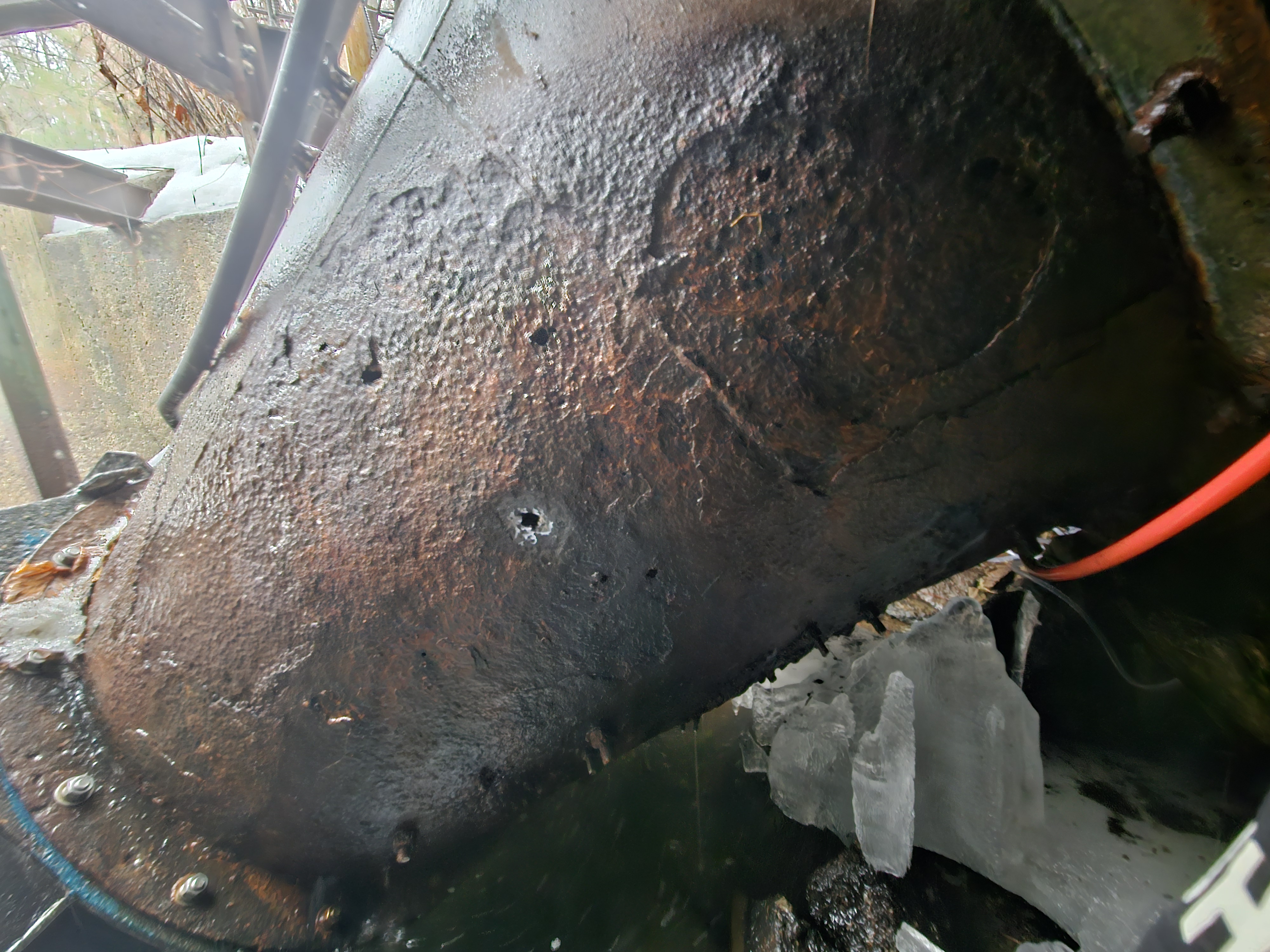
So for most of this turbines life the tailrace of the river was about 2ft higher than it is now. So when the turbine was in operation this tapered piece sat in the water. In about 2015 or so the previous owner dig out the tailrace 2ft to get some extra power. So now when the turbine is on this part of the taper is exposed. And as you can tell the originally half inch or so steel is sorta gone. maybe about a dozen or so half in holes.
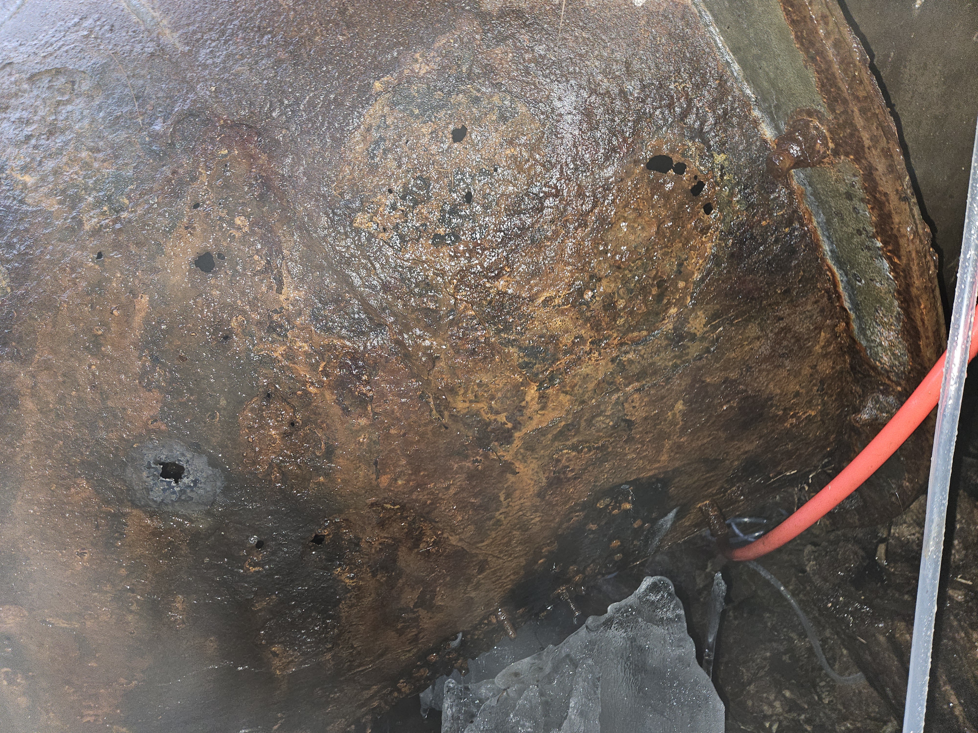
Holes are generally not good in your pressurized water penstock. But we really arent asking for much on this turbine setup, but when the turbine is going these holes are all little mini pressure washers going out the side which is not ideal.
Now, this is in January. And I was working on this penstock area and I had my phone in my breast jacket pocket. And I was climbing around and I leaned forward and woosh. Phone falls out of my pocket and into the turbine exit area underwater. I was devistated because This was a new to me phone as of a couple days. It was still slightly light out, and because of that I couldnt see anything under the water because of the sky gray reflection. We have a long rake for cleaning the trash rack, so I went fishing to try to scoop up my phone. But I knew that I couldnt see it when it was light out. So I suited up in a wetsuit a friend gave me for doing odd things. I was fully suited up ready to dive in if I could see the phone. So I had an idea, we have some chinese LED lights that say they are IP rated. I figured a light was worth sacrificing to find my phone. So I tied the light to the giant long rake, and I was able to see under the water , as its crystal clear. I spent maybe an hour fishing around and looking and raking around, mind you the rake is about 10ft underwater. And wala let the video do the talking. Click the video for audio. I recorded the video on my buddy Nicks phone, who came to help. It seems as if I caught the phone and flipped the screen up and I saw the glimmer. With one fell swoop i scooped the phone onto the rake pulled it up. Got the phone in my hands and its probably 32.1 degrees freezing cold, and press the power button and it opens to the lock screen. I was so relieved. Once the phone warmed up it was less happy and clearly had moisture in it. So I put it in a jar of scilica gel and rice, and lightly toasted. The phone came back to life, but the camera modules had moisture in them. So I smashed the glass dried them out and put new glass on. The phone has been find ever since.
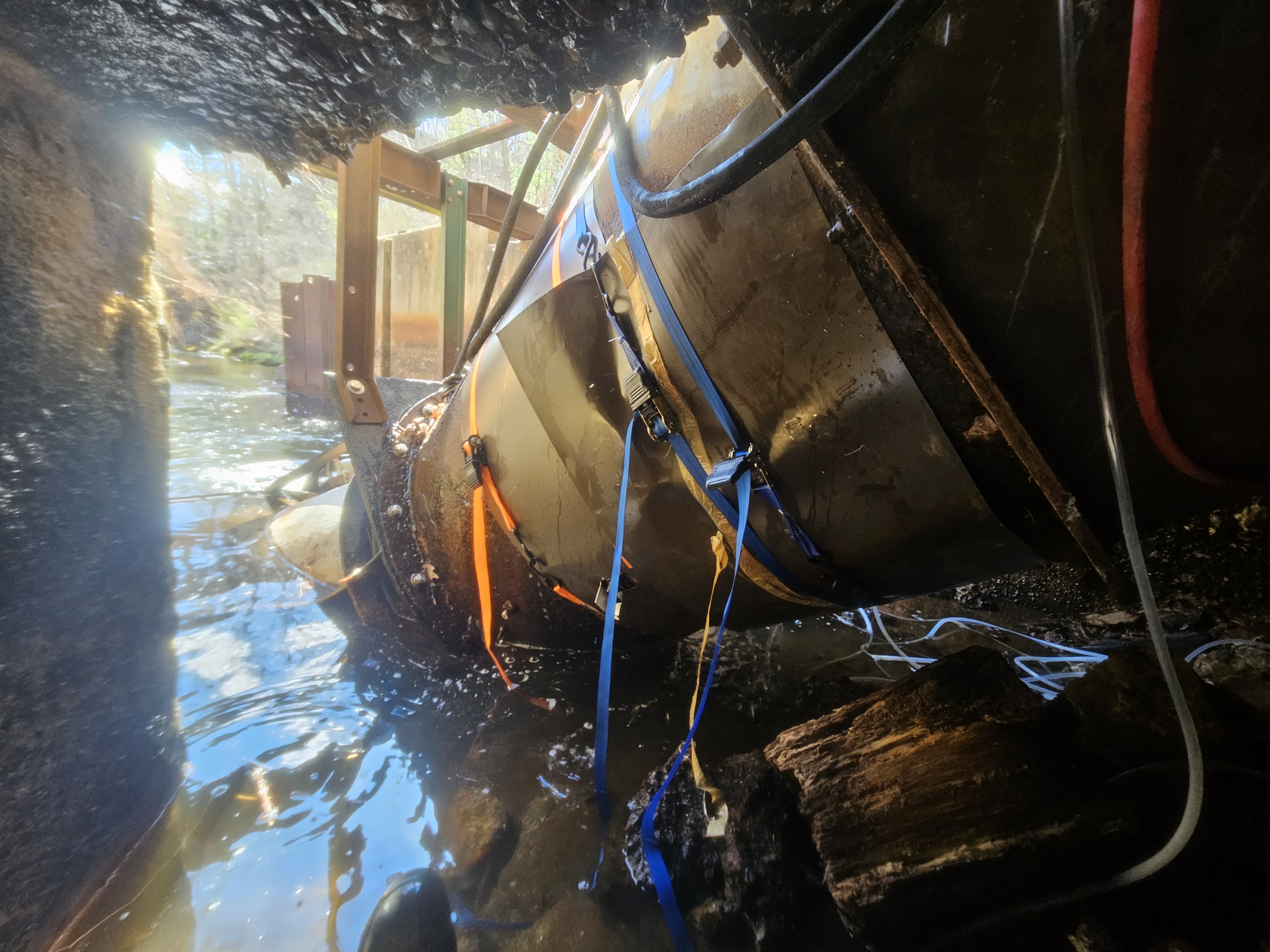
So how do you fix the holes in the taper? Magic goo, aluminum flashing, and ratched straps. I tried to clean the holes and lather this flex seal putty in the holes and then put the flashing around the taper and ratchet strap it into place. It works suprisingly well. The goal is not to seal the holes per se, but to just make it so that its not pressure washing out the sides and hitting the building. This steel penstock also doesnt actually see that much stress on it from weight. Above this section is a straight section that is held in place by a beam, and the turbine on the front and back are held up by little C beams. So this taper has just enough metal to sorta exist. Also why not make a new one? It was disucussed, but inside this taper are swirling vanes of some angle, that match some magic angle on the propellor so that there optimal water angle at one specific propellor pitch, what are any of those angles? No friggin idea. Realisitically we want this turbine to function for about a year before we can replace it for another one, that is more reliable and or efficient or just one that doesnt have holes in it.